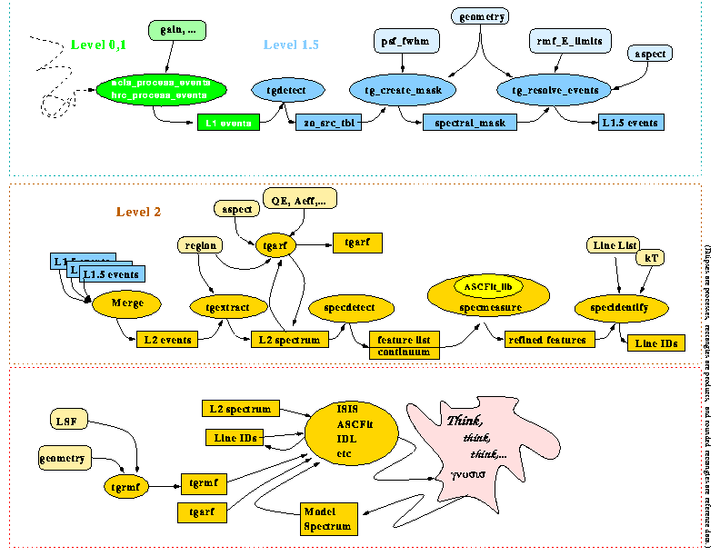
- Pipeline data flow -
- all the steps, inputs, and products to go from event-lists, to diffraction coordinates, to binned spectra, and simple measurements for both HETG and LETG.
- Graphical examples -
- some views of the data, test cases.
- Data product descriptions -
- detailed descriptions of the data products, if you really want to know.
- Issues -
- unfinished, unresolved, ...
- Credits -
- who does what.
- Information -
- some links, for more details.
Pipeline Data Flow
Graphical Examples
This is a view of photon locations ( not intensity!) for a simulation with 2 sources separated by 1.7 arcmin. The upper source is the more-northern. The sky coordinates were determined by acis_process_events (without dither).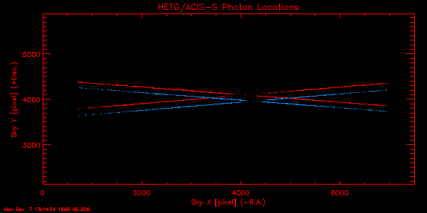
This is a close-up of the zero-order region, showing the
default regions, as calculated by tg_create_mask. Note the region
where the MEG positive orders of the upper source cross the HEG positive
orders of the lower source. There is also a chip-gap visible near
x=4900.
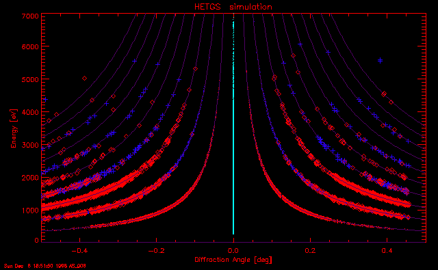
Orders are sorted (for ACIS) by using the CCD redistribution
function to determine limits in PI (linearized to energy) expected for
each order at each diffraction angle. This is the distribution in diffraction
coordinates.
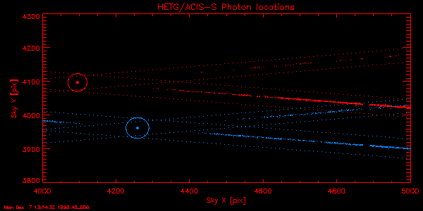
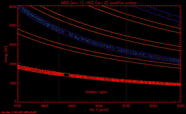
A close-up of the region where one source's MEG order
cross the other's HEG is shown here:
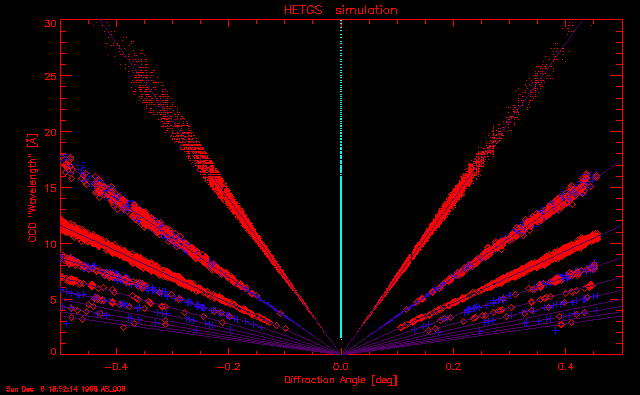
This view is similar to the last, except that the CCD
PI values have been converted into a linearized CCD ``Wavelength''.
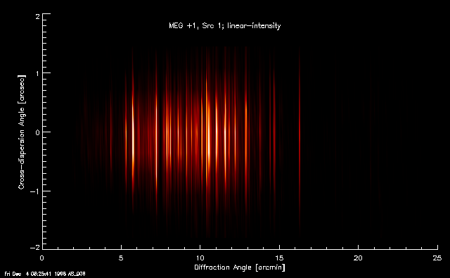
This is an intensity image of the MEG first order for
one source, made by binning the angular dispersion and cross-dispersion
coordinates (TG_R, TG_D) in the Level 1.5
event file:
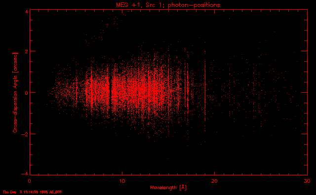
This is a photon-position scatterplot of the same spectrum
in wavelength coordinates:
Finally, we bin the spectrum into a ``Type II PHA'' file,
in which each row holds a spectrum for a specific order, source, and grating.
Background spectra are also binned. Here is the combined first-order MEG
spectrum, with insets showing expanded views of 2 one-Angstrom regions,
and the corresponding HEG counts spectrum for one region. (``Type I PHA''
output is also an option.)

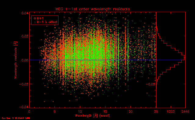
How do we know the results are correct? Test, test, test,
test, ... For example, we know wavelengths
a priori in marx,
so we can compare to the derived value. The figure shows the residuals
( ) for MEG +1 (diamonds)
and -1 (dots). ... and we notice an offset by about
) for MEG +1 (diamonds)
and -1 (dots). ... and we notice an offset by about  pixel, and maybe a slope.
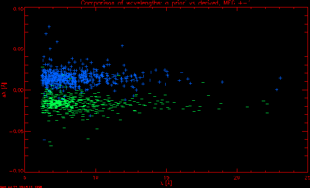
The previous is much improved over the July, 1998 case
here. The large difference between plus and minus orders was due to a zero-order
mis-placement.
Data Products
Level 1.5
``Level 1.5'' processing refers to the determination of zero-order centroids, definition of spectral regions, and computation of diffraction coordinates. The resulting products are a source table, an augmented event-list, and a region, with the event-list being the fundamental product.
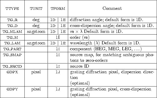
The region is used to classify the ``Level 1'' events according to the part of the spectrum. Then the events' detector positions of diffracted photons are transformed to diffraction coordinates using the zero-order centroid as the origin, after transforming it from sky coordinates to instantaneous detector coordinates using the aspect solution. The attributes of each photon thus determined are appended to the event-list as new columns:
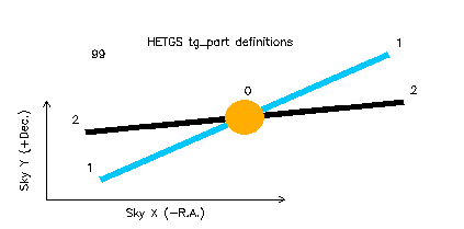
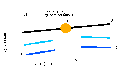
The part definitions are shown in these schematics of
the different regions. For multiple sources, each source will have a set
of parts defined. (1 => HEG, 2 => MEG)
For LETG with HRC-S, the HESF parts are only present if
a source is incident on the flat (either by being off-axis, or by intentional
placement of the detector).
Level 2
Level 2 is primarily defined by derivation of ``secondary'' products, particularly those which yield physical information upon inspection --- such as an image, or a spectrum, or a light-curve. Level 2 also refers to measurement products, such as fluxes. Hence, instrumental responses are also Level 2.
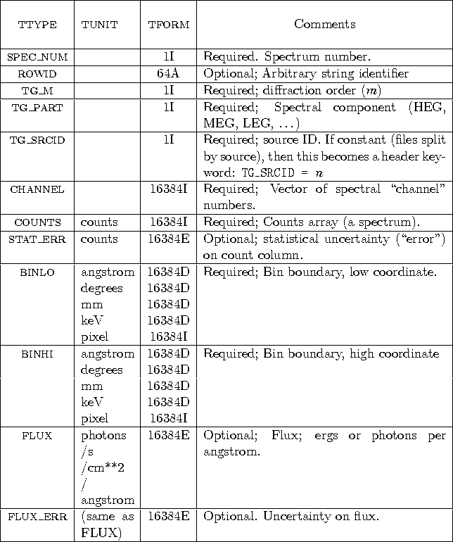
After event-lists are merged over any multiple observation intervals, photons are binned into 1-dimensional spectra vs. source-ID, part, and order. The output format is a Type II ``PHA'' file, with slight modifications to include AXAF grating-related information. (The file format is, in fact, compatible with XSPEC.) The structure is defined, in part, as follows:
The Effective Area (``ARF'')
We need an effective area for each source, spectral part, and order. This also depends upon the aspect history, since parts of the spectrum fall in gaps, or on detector regions of different sensitivity. We have defined a ``Type II ARF'', in analogy with the Type II PHA file (ARF = Auxiliary Response Function), and uses the same spectral labeling columns as the PHA file: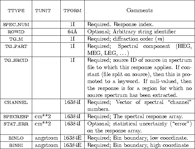
Grating Redistrubution Function
An ``RMF'' (Redistribution Matrix Function) will be defined for HETG and LETG. This is in the same form as the OGIP, except that it redistributes from wavelength (or energy) into position, and so encodes the Line Spread Function (LSF). We may add a column to hold the diffraction order which goes with each group. (Or we may find it more useful to call a function to return the profile for the desired energy, order, off-axis-angle, ...).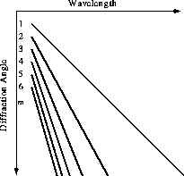
Other Products
There are other supporting products, which will only be listed here, without details:- source table
- - positions of zero-order centroids in sky coords, used by tg_create_mask.
- sky region
- - for filtering photons during tg_resolve_events (both ASCII and FITS versions).
- binning region
- - for filtering photons in diffraction coordinates for binning into 1D spectra.
- spectral features
- - detected peaks table.
- measured features
- - fits to detected peaks.
- identified features
- - table of matches of measured features to line-list.
Some Issues
In no particular order some items remaining to be implemented or specified are:- continuous-clocking mode processing specs and calibration
- HESF mask implementation
- zero-order blocking, and coordinate system reference
- RMF usage; too big? function better?
- HRC filter shadows and calibration
- 2D analysis, optimal extraction
- LETG recursion for order-resolution
-
3D response (
 )
analysis
)
analysis - Extended source analysis
- Variable source analysis
Credits
Some of those more directly involved with the grating processing are:- Software specification:
- David Huenemoerder: pipeline event processing tools, binning tools
- John Houck: pipeline line tools.
- Michael Wise, David Davis: RMF, PSF tools
- John Davis: ARF Tools
- Dan Dewey, Herman Marshall, Jeremy Drake: Calibration consultants.
- Software coding:
- Anastasia Alexov: pipeline tools, line tools
- Warren McLaughlin: pipeline tools
- Helen He: RMF tools
- Kenny Glotfelty: PSF tools.
- John Davis: ARF tools
More Information
For more information, check the following:- Detailed specification of data products are in ``Interface Control Documents''. Some relevant to gratings can be found at
- A ``How-To'' guide to using the ASCDS tools:
- A gallery of planned HETG observations:
- Norberts's AXAF Science Page:
- An overview of grating processing (somewhat dated, and yet to be updated):
- This document, and hypertext version: TBD. Look for it in:
http://space.mit.edu/ASC/docs/docs.html
http://space.mit.edu/ASC/analysis/TG_HowTo/TG_HowTo.html
http://space.mit.edu/ASC/science/science.html
http://space.mit.edu/%7Enss/axaf.html
http://space.mit.edu/ASC/analysis/L1.5_overview/L15.html
http://space.mit.edu/ASC/analysis/analysis.html
About this document ...
This document was generated using the LaTeX2HTML translator Version 95.1 (Fri Jan 20 1995) Copyright © 1993, 1994, Nikos Drakos, Computer Based Learning Unit, University of Leeds.The command line arguments were:
latex2html -t TG Processing How-To Guide -split
0 -link 0 tg_headcc3.tex.
The translation was initiated by David Huenemoerder on
Mon Dec 7 12:09:20 EST 1998 and the output hacked into the form
you see here.
David Huenemoerder
(617) 253-4283
Mon Dec 7 12:09:20 EST 1998