HETG: Basic Design
HETG: Basic Design
(updated 11/10/97)
Go to HETG at XRCF
HETG Design
IDL routines were used to generate the data needed as input
to the CAD process to design the HETG Support Structure (HESS).
Through excellent engineering (Chris Pak and Mike McGuirk) and
fabrication (Brenner (PA)) the as-built HETG is very close
to the ideal design.
The definitions and uses of the data above are clarified in the
Figures and captions below.
HETG as-built, FCPs
The design values above will be adjusted based on the actual
HESS metrology (if warranted) and especially to take into
account the grating roll values (specifically the MEG
mis-aligned gratings). So we have the following planned improvement:
- HESSbuilt.rdb Same as HESSdesign.rdb but with
rotated grating-line and dispersion-direction unit
vectors to account for the MEG mis-aligned gratings and
the statistical mis-alignements (to be derived from XRCF data.)
Possibly also adjusted facet locations and angles based on metrology.
CIPs
Based also on this s/w we have created a basic data file
hetg*basicNxxxx.rdb which contains
some general and higher-level products of direct use in
routine data analysis and modeling.
- Designed Rowland Diameter is = 8633.69 mm.
- The vignetting factors for each shell are calculated
based on the grating-grating spacing and grating frame dimensions.
- The effective ring radii ( hs_X*TAN(theta_shell) ) or
cone angles (theta_shell) which are parameters used to estimate the astigmatism
and defocus blur.
Figures
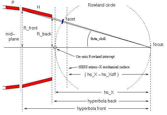
Figure hess.1 HRMA, Rowland geometry parameters-
The HETG design must place facets on the Rowland
torus and intercept the rays from the HRMA. Parameters in hess_setup.pro
defined the HRMA ray cones. The Rowland torus is defined by the
focus location and the Rowland diameter, hs_X, the distance from the
focus to the on-axis Rowland circle intercept. The HESS design
uses as its X (axial) origin a plane offset from the intercept
by a distance of hs_Xoff; this plane is also a physical mechanical
surface of the HETG. Thus, to convert the X locations tabulated in
HESSdesign.rdb into distances from the (design) focus: add
(hs_X - hs_Xoff).

Figure hess.2 Facet frame parameters-
This schematic of an HETG grating frame is viewed along
the minus-X direction, that is as seen by an approaching X-ray.
The goal of the HESS design is to put the center of the
facet active area on the Rowland torus with the facet
membrane normal to the HRMA ray through the facet center.
The parameters hs_Doff, hs_Dspc, and hs_Dthk (not shown)
were used to map the membrane centers to the mounting
hole locations. Facet coordinates in the membrane plane
are shown here, Xf and Yf.
For ray-tracing, the dot products of Xf and Yf with
the {point of intersection of the ray with the facet plane
minus the facet center location} gives the the intersection
coordinates in frame coordinates, (Xf,Yf)_intersection.
Using the geometry above and the values of hs_Alen
(in hess_setup.pro) the fate of an X-ray that intersects
near the grating can be determined with the steps below
(the first satisfied criteria is the result):
| Condition | Result |
|---|
| Xf > 0.5*hs_Alen + 25.4*0.070 OR |
|
| Xf < 0.5*hs_Alen - 25.4*0.030 | outside of this grating's domain
|
| |Xf| < 0.5*hs_Alen AND |
|
| |Yf| < 0.5*hs_Alen | interacts with active area of this facet
|
| Yf > 0.5*hs_Alen + 25.4*0.030 | passes uneffected (unless Yf much larger)
|
| Yf < 0.5*hs_Alen - 25.4*0.104 | might hit HESS or be uneffected
|
| (otherwise) | absorbed by frame
|